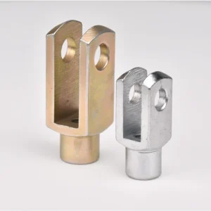
Pinned Rod and Cylinder Connections
Clevis ends create a straightforward pinned connection for rods, actuator eyes, and cylinder attachments where the clevis pin provides the pivot. Check pin fit, side clearance, shear load, and retention details.
Busque por número de pieza, serie, material, aplicación o especificación.
Pulsa Enter para ver todos los resultados Esc para cerrar

 metric-related-product
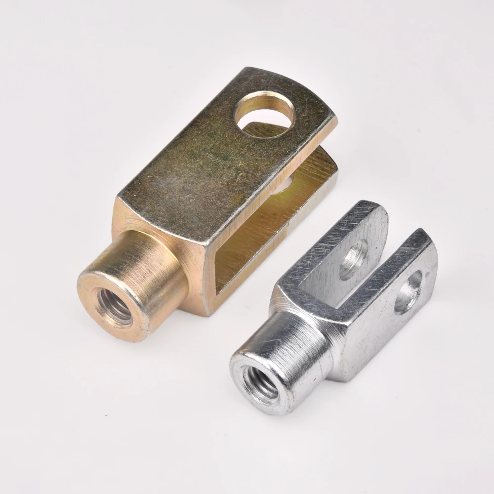
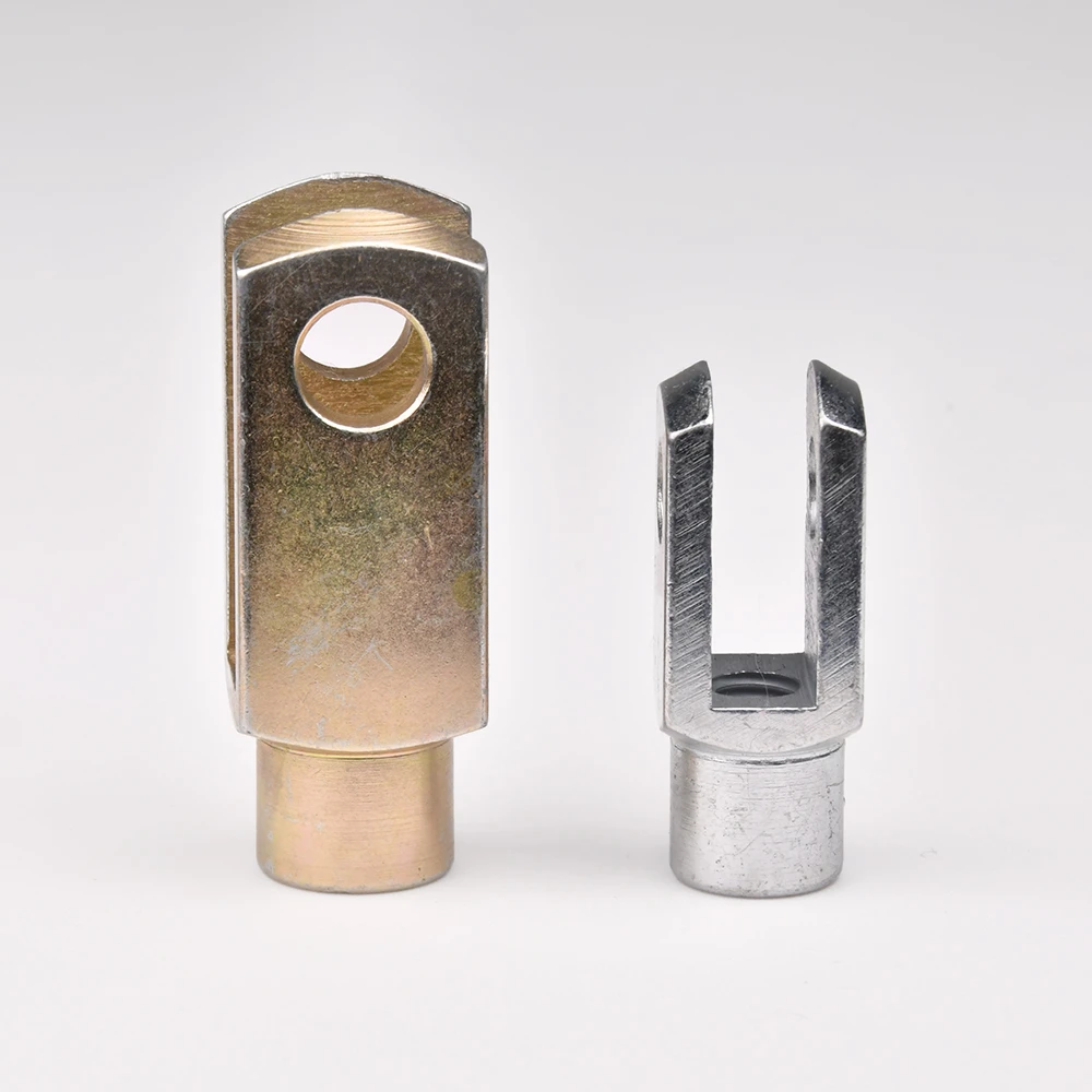
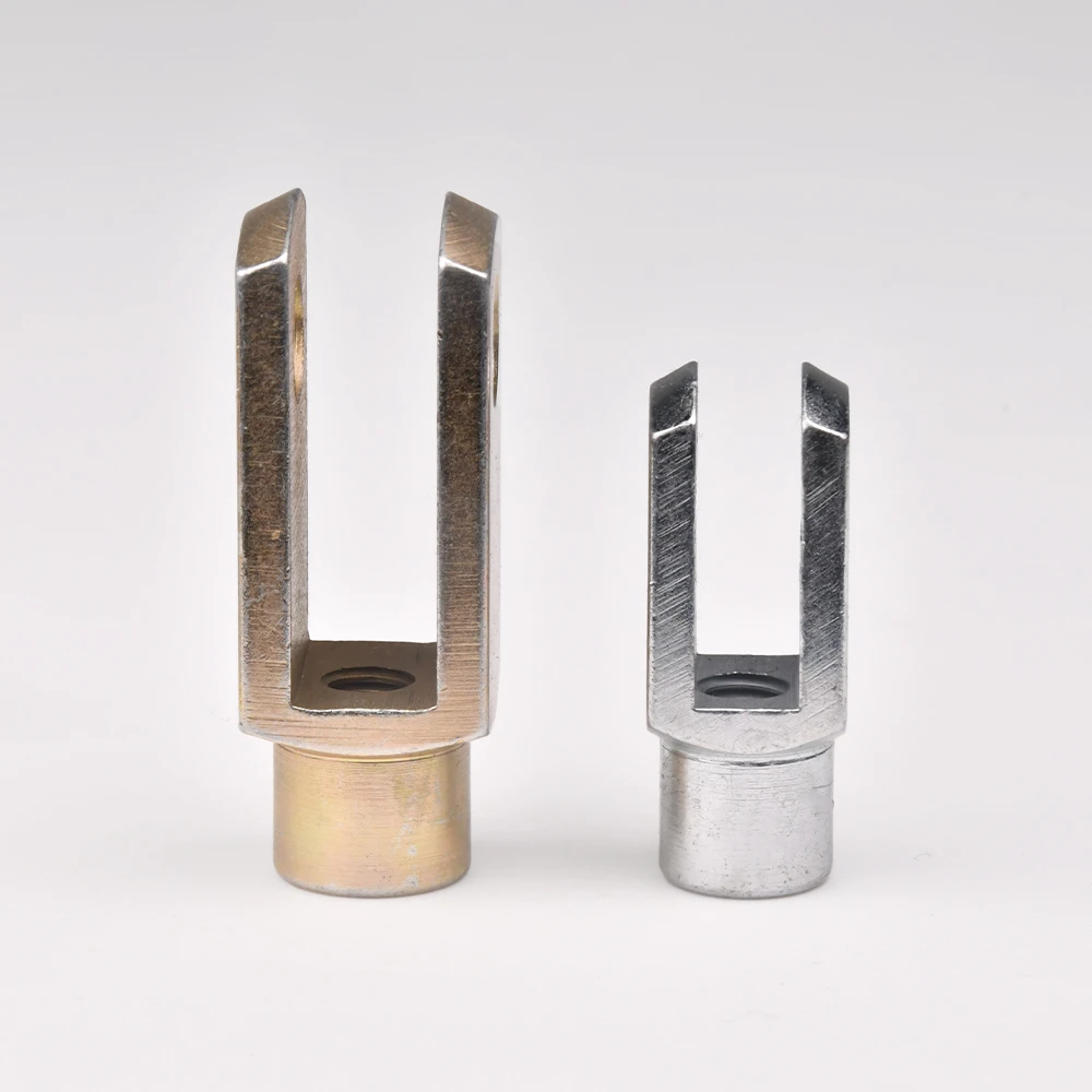
G 12x48FG es una horquilla métrica de la serie G con rosca M12×1.25 (rosca de paso fino), orificio para pasador de 12 mm (d1) y longitud de pasador de 48 mm (l1). Ancho del cuerpo (w3) = 24 mm, longitud total del cuerpo (l2) = 86 mm. Peso aproximado: 175 g.
Fabricada en acero Q235 con zincado plateado. La horquilla de la serie G es un accesorio de horquilla hembra que aloja un pasador de horquilla a través del orificio, permitiendo una conexión articulada a un soporte de acoplamiento o a un ojal de eslabonamiento. El extremo roscado se conecta a un actuador métrico, a un vástago de cilindro o a un adaptador de tubo. Se utiliza en eslabonamientos de cilindros neumáticos, controles de automatización, actuadores de válvulas y conjuntos de horquillas métricas de uso general.
Disponible con rosca izquierda: añada el sufijo ‘LH’ (p. ej., G×12x48FGLH). Versiones de acero inoxidable y aluminio disponibles bajo pedido. Pasador de horquilla, arandela y pasador de chaveta disponibles por separado. Opción de horquilla con pasador de resorte disponible.
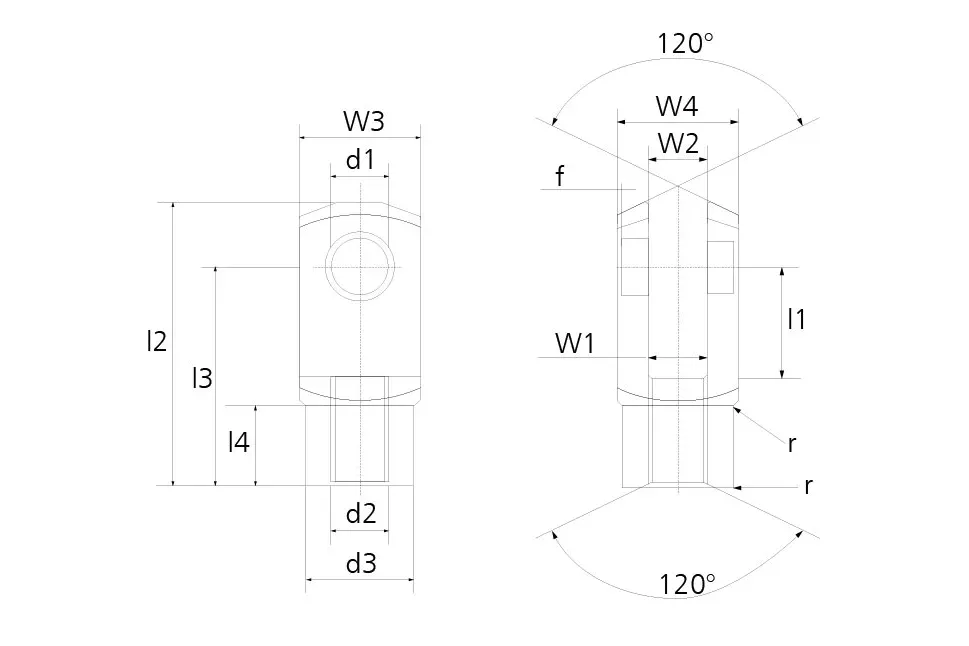
All available sizes in the G CLEVIS METRIC series. Can’t find your size? Contact us for custom dimensions.
| Part NO. | THREAD d2 | d1 H9 | l1 +0.5 -0.5 | w3 | w4 | w1 | w2 | d3 | l2 +0.5 -0.5 | l3 | l4 | APPROX WEIGHT (GRAM) |
|---|---|---|---|---|---|---|---|---|---|---|---|---|
| G 4x8 | M4 | 4 | 8 | 8 | 8 | 4 | 4 | 8 | 21 | 16 | 6.0 | 5 |
| G 4x16 | M4 | 4 | 16 | 8 | 8 | 4 | 4 | 8 | 29 | 24 | 6.0 | 7 |
| G 5x10 | M5 | 5 | 10 | 10 | 10 | 5 | 5 | 9 | 26 | 20 | 7.5 | 9 |
| G 5x20 | M5 | 5 | 20 | 10 | 10 | 5 | 5 | 9 | 36 | 30 | 7.5 | 13 |
| G 6x12 | M6 | 6 | 12 | 12 | 12 | 6 | 6 | 10 | 31 | 24 | 9.0 | 15 |
| G 6x24 | M6 | 6 | 24 | 12 | 12 | 6 | 6 | 10 | 43 | 36 | 9.0 | 21 |
| G 8x16 | M8 | 8 | 16 | 16 | 16 | 8 | 8 | 14 | 42 | 32 | 12.0 | 37 |
| G 8x16FG | M8X1 | 8 | 16 | 16 | 16 | 8 | 8 | 14 | 42 | 32 | 12.0 | 37 |
| G 8x32 | M8 | 8 | 32 | 16 | 16 | 8 | 8 | 14 | 58 | 48 | 12.0 | 54 |
| G 8x32FG | M8X1 | 8 | 32 | 16 | 16 | 8 | 8 | 14 | 58 | 48 | 12.0 | 54 |
| G 10x20 | M10 | 10 | 20 | 20 | 20 | 10 | 10 | 18 | 52 | 40 | 15.0 | 74 |
| G 10x20FG | M10X1.25 | 10 | 20 | 20 | 20 | 10 | 10 | 18 | 52 | 40 | 15.0 | 74 |
| G 10x40 | M10 | 10 | 40 | 20 | 20 | 10 | 10 | 18 | 72 | 60 | 15.0 | 116 |
| G 10x40FG | M10X1.25 | 10 | 40 | 20 | 20 | 10 | 10 | 18 | 72 | 60 | 15.0 | 116 |
| G 12x24 | M12 | 12 | 24 | 24 | 24 | 12 | 12 | 20 | 62 | 48 | 18.0 | 121 |
| G 12x24FG | M12X1.25 | 12 | 24 | 24 | 24 | 12 | 12 | 20 | 62 | 48 | 18.0 | 121 |
| G 12x48 | M12 | 12 | 48 | 24 | 24 | 12 | 12 | 20 | 86 | 72 | 18.0 | 175 |
| G 12x48FG | M12X1.25 | 12 | 48 | 24 | 24 | 12 | 12 | 20 | 86 | 72 | 18.0 | 175 |
| G 14x28 | M14 | 14 | 28 | 27 | 27 | 14 | 14 | 24 | 72 | 56 | 22.5 | 178 |
| G 14x28FG | M14X1.5 | 14 | 28 | 27 | 27 | 14 | 14 | 24 | 72 | 56 | 22.5 | 178 |
| G 14x56 | M14 | 14 | 56 | 27 | 27 | 14 | 14 | 24 | 101 | 85 | 22.5 | 258 |
| G 14x56FG | M14X1.5 | 14 | 56 | 27 | 27 | 14 | 14 | 24 | 101 | 85 | 22.5 | 258 |
| G 16x32 | M16 | 16 | 32 | 32 | 32 | 16 | 16 | 26 | 83 | 64 | 24.0 | 282 |
| G 16x32FG | M16X1.5 | 16 | 32 | 32 | 32 | 16 | 16 | 26 | 83 | 64 | 24.0 | 282 |
| G 16x64 | M16 | 16 | 64 | 32 | 32 | 16 | 16 | 26 | 115 | 96 | 24.0 | 411 |
| G 16x64FG | M16X1.5 | 16 | 64 | 32 | 32 | 16 | 16 | 26 | 115 | 96 | 24.0 | 411 |
| G 18x36 | M18 | 18 | 36 | 36 | 36 | 18 | 18 | 30 | 94 | 72 | 27.0 | 390 |
| G 18x36FG | M18X1.5 | 18 | 36 | 36 | 36 | 18 | 18 | 30 | 94 | 72 | 27.0 | 390 |
| G 20x40 | M20 | 20 | 40 | 40 | 40 | 20 | 20 | 34 | 105 | 80 | 30.0 | 550 |
| G 20x40FG | M20X1.5 | 20 | 40 | 40 | 40 | 20 | 20 | 34 | 105 | 80 | 30.0 | 550 |
| G 20x80 | M20 | 20 | 80 | 40 | 40 | 20 | 20 | 34 | 145 | 120 | 30.0 | 800 |
| G 20x80FG | M20X1.5 | 20 | 80 | 40 | 40 | 20 | 20 | 34 | 145 | 120 | 30.0 | 800 |
| G 25x50 | M24 | 25 | 50 | 50 | 50 | 25 | 25 | 42 | 132 | 100 | 36.0 | 1100 |
| G 25x50FG | M24X2 | 25 | 50 | 50 | 50 | 25 | 25 | 42 | 132 | 100 | 36.0 | 1100 |
| G 28x56 | M27 | 28 | 56 | 55 | 55 | 28 | 28 | 48 | 148 | 112 | 40.0 | 1500 |
| G 28x56FG | M27X2 | 28 | 56 | 55 | 55 | 28 | 28 | 48 | 148 | 112 | 40.0 | 1500 |
| G 30x54FG | M27X2 | 30 | 54 | 55 | 55 | 30 | 30 | 48 | 148 | 110 | 40.0 | 1440 |
| G 30x60 | M30 | 30 | 60 | 60 | 60 | 30 | 30 | 52 | 160 | 120 | 42.0 | 1970 |
| G 30x60FG | M30X2 | 30 | 60 | 60 | 60 | 30 | 30 | 52 | 160 | 120 | 42.0 | 1970 |
| G 35x54FG | M36X2 | 35 | 54 | 70 | 70 | 35 | 35 | 60 | 188 | 144 | 54.0 | 2930 |
| G 35x72 | M36 | 35 | 72 | 70 | 70 | 35 | 35 | 60 | 188 | 144 | 54.0 | 2930 |
| G 35x72FG | M36X2 | 35 | 72 | 70 | 70 | 35 | 35 | 60 | 188 | 144 | 54.0 | 2930 |
| G 36x72 | M36 | 35 | 72 | 70 | 70 | 36 | 36 | 60 | 188 | 144 | 54.0 | 2930 |
| G 36x72FG | M36X2 | 35 | 72 | 70 | 70 | 36 | 36 | 60 | 188 | 144 | 54.0 | 2930 |
| G 40x84FG | M42X2 | 40 | 84 | 85 | 85 | 40 | 40 | 70 | 232 | 168 | 63.5 | 5640 |
| G 42x84 | M42 | 42 | 84 | 85 | 85 | 42 | 42 | 70 | 232 | 168 | 63.5 | 5340 |
| G 42x84FG | M42X2 | 42 | 84 | 85 | 85 | 42 | 42 | 70 | 232 | 168 | 63.5 | 5340 |
| G 50x96 | M48 | 50 | 96 | 96 | 96 | 50 | 50 | 82 | 265 | 192 | 73.0 | 7860 |
| G 50x96FG | M48X2 | 50 | 96 | 96 | 96 | 50 | 50 | 82 | 265 | 192 | 73.0 | 7860 |
Material certifications verified. Composition confirmed by spectrometer before machining begins.
100% go/no-go gauge check on all threaded sections. Zero tolerance on dimensional non-conformance.
Static and dynamic load tests run on representative samples from each production batch.
CMM verification of critical dimensions — ball diameter, bore, thread pitch, and body length.
Visual and tactile inspection for burrs, scratches, surface cracks, and plating defects.
Misalignment angle and torque measured to confirm liner performance meets specification.
Hardness tests confirm proper heat treatment on chromoly steel bodies and bearing balls.
Full traceability from raw material heat number to finished part. COC and inspection reports available.
Share your part number, required quantity, and any special material or packaging requirements. We respond within 24 hours.
The G 12x48FG is a metric G-series clevis with a M12×1.25 fine-pitch threaded stud end and a 12 mm pin bore, built as a female fork fitting for pneumatic cylinder linkages, automation controls, valve actuators, and general-purpose metric clevis assemblies. The threaded end connects to a mating actuator, cylinder rod, or tube adapter, while the bore accepts a clevis pin so the fitting can pivot against a bracket or linkage eye.
The G 12x48FG and G 12x48 share the same 12 mm pin bore and 48 mm pin length — the difference is thread pitch. The G 12x48FG is the fine-pitch version, threaded M12×1.25, while the G 12x48 uses the standard M12 thread. Pick whichever pitch matches the mating actuator, cylinder rod, or tube adapter you're connecting to.
Pin bore (d1) is 12 mm and pin length (l1) is 48 mm, sized to take a 12 mm clevis pin through the fork bore for the articulated connection.
Overall body length (l2) is 86 mm, body width (w3) is 24 mm, hub diameter (d3) is 20 mm, and fork throat depth (l4) is 18.0 mm. Approximate weight is 175 g (0.17 kg) — check these against your linkage clearance and handling requirements before ordering.
Standard construction is Q235 steel with a silver zinc-plated finish. Stainless steel and aluminum versions are available on request — confirm material and finish when requesting a quote.
Yes. Standard thread hand is right-hand; add "LH" to the part number (e.g., G×12x48FGLH) to order the left-hand thread version for turnbuckle-style or opposing-thread linkage builds. Clevis pin, washer, and cotter pin are available separately, and a spring-pin clevis option is also offered.